
We are thrilled to introduce the latest technical bulletin tailored exclusively for the AUDI , Model AUDI (8V1, 8KV), Version 1.6 TDI (CRKB) 81 KW 110 CV 1598 Cm3. This comprehensive bulletin has been meticulously crafted to offer you detailed procedures and precise instructions, serving as an indispensable resource for all your maintenance and troubleshooting needs.
SYMPTOMS:
21186 – P189A – Clutch 1. Clearance too small.
10121 – P2789 – Clutch 2. Travel of P4 too small.
P177C – Clutch 2. Tolerance limit reached.
P177D – Dual clutch. Excessive torque.
P189B – Clutch 2. Clearance too small.
P177B – Clutch 1. Tolerance limit reached.
P0810 – Clutch activation. Malfunction.
The vehicle displays one or several of the above-mentioned fault codes.
Fault codes recorded in the gearbox control unit.
The engine jerks or rattles when starting or when automatically shifting from 1st to 2nd speed.
The transmission warning light comes ON sporadically.
The gearbox enters into degraded or emer- gency mode, only the 1st, 3rd, 5th and 7th or 2nd, 4th, 6th, and R gears are switched.
NOTE: One or several symptoms may be reproduced in the workshop.
POSSIBLE CAUSES:
- Defect in the clutch.
- Defect in the hinge bracket
SOLUTION :
Repair procedure:
- Read the fault codes recorded in the control unit using the diagnostic tool.
- Confirm that one or several of the fault codes that appear in the field symptoms of this bulletin are displayed.
- Confirm that the symptoms mentioned in the field symptoms of this bulletin are reproduced.
- Remove the gearbox.
- Remove the dual clutch.
- Unscrew the bolt with a washer (See image 1 – A).
- Place the dual clutch on the tensioner (See image 1 – B).
- Screw the previously unscrewed bolt with a washer into the tensioner and tighten (See image 1 – C).
Retract clutch K1:
- Insert 3 flat-head screwdrivers (See image 1 – D) between the drive ring (See image 1 – E) and the pressure plate (See image 1 – F).
- Turn the dual clutch with the 3 flat-head screwdrivers inserted (See image 1 – G).
- Retract the clutch disc adjusting screw K1 (See image 1 – H) with two conventional flat-head screwdrivers in the direction of the arrow (See image 1 – I and J). Then, hold the two flat-head screwdrivers in this position and remove the 3 flat-head screwdrivers from below (See image 1 – K).
Retract clutch K2:
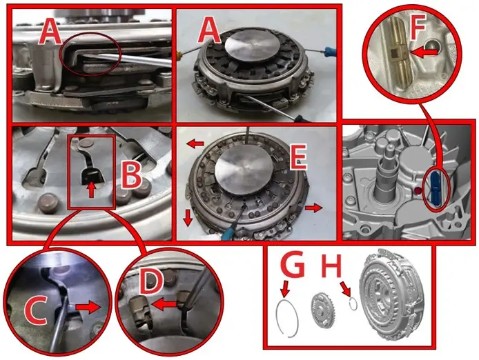
- Insert 3 flat-head screwdrivers between the clutch cover K2 and the pressure plate K2 (See image 2 – A).
- Retract the adjustment ring of clutch disc K2 (See image 2 – B) with two flat-head screwdrivers in the direction of the arrow (See image 2 – C and D). Then, hold the two flat-head screwdrivers in this position and remove again the 3 flat-head screwdrivers from below (See image – E).
- Remove the 2 remaining flat-head screwdrivers.
- Check that clutch discs K1 and K2 move freely.
- If the discs move freely, remove the tensioner. If, on the contrary, the discs DO NOT move freely, the dual clutch must be retracted.
- Thoroughly clean the gearbox housing in the hinge bracket area.
- Mark the mounting position of the hinge bracket with a marker (See image 2 – F).
- Remove the hinge bracket.
- Thoroughly clean the adjustment drills in the gearbox housing.
- Thoroughly clean the reverse side of the hinge bracket and apply a fixative liquid recommended by the manufacturer.
- Insert again the hinge bracket into the gearbox housing with the help of a hammer and a piece of wood.
- Fit the dual clutch in the gearbox.
- Install the gearbox.
- Clear the fault codes recorded in the control unit using the diagnostic tool.
- Carry out a second fault code reading of the gearbox control unit using the diagnostic tool and con- firm that NO fault codes are recorded.
- Carry out a function test.
IMPORTANT: The security ring (See image 2 – G) can be reused if it is not damaged.
IMPORTANT: The small security ring (See image 2 – H) must be replaced imperatively.
NOTE: For a correct repair, it is recommended to follow the instructions in the repair manual.
A – K2 pressure plate.
B – Dual clutch.
C – Screw with a washer.
D – Flat-head screwdrivers.
E – Drive ring.
F – Pressure plate.
G – Dual clutch upside down.
H – Adjustment screw of clutch disc K1.
I – Direction.
J – Direction.
K – Flat-head screwdrivers from below.
See image 2:
A – K2 pressure plate.
B – Adjustment ring of clutch disc K2.
C – Direction.
D – Direction.
E – Flat-head screwdrivers from below.
F – Hinge bracket.
IMAGE 1 :
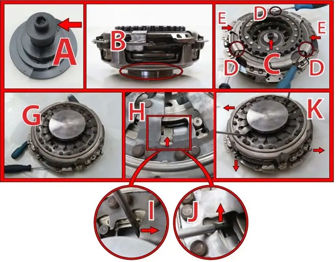
IMAGE 2 :
We urge you to take full advantage of Mecainfo‘s TSB (Technical Solutions Bulletin). This exceptional resource houses pre-established solutions for commonly faced issues, serving as a valuable knowledge repository to assist you effectively in your maintenance and troubleshooting pursuits.